Published by HALOX Co.
What a connecting rod actually does
A connecting rod transfers piston force to a crankpin. The small end takes the piston pin, the big end holds the bearing inserts, and a bent shank in a photo does not name the load that bent it.
The piston moves in a line. The connecting rod takes that shove to a journal offset from the crank’s centerline. The offset is the throw, and the rod is not the shaft. Motorservice follows the gas and inertia loads to the crankpins. Turning is the crankshaft’s job. The flywheel is at the other end of that shaft.
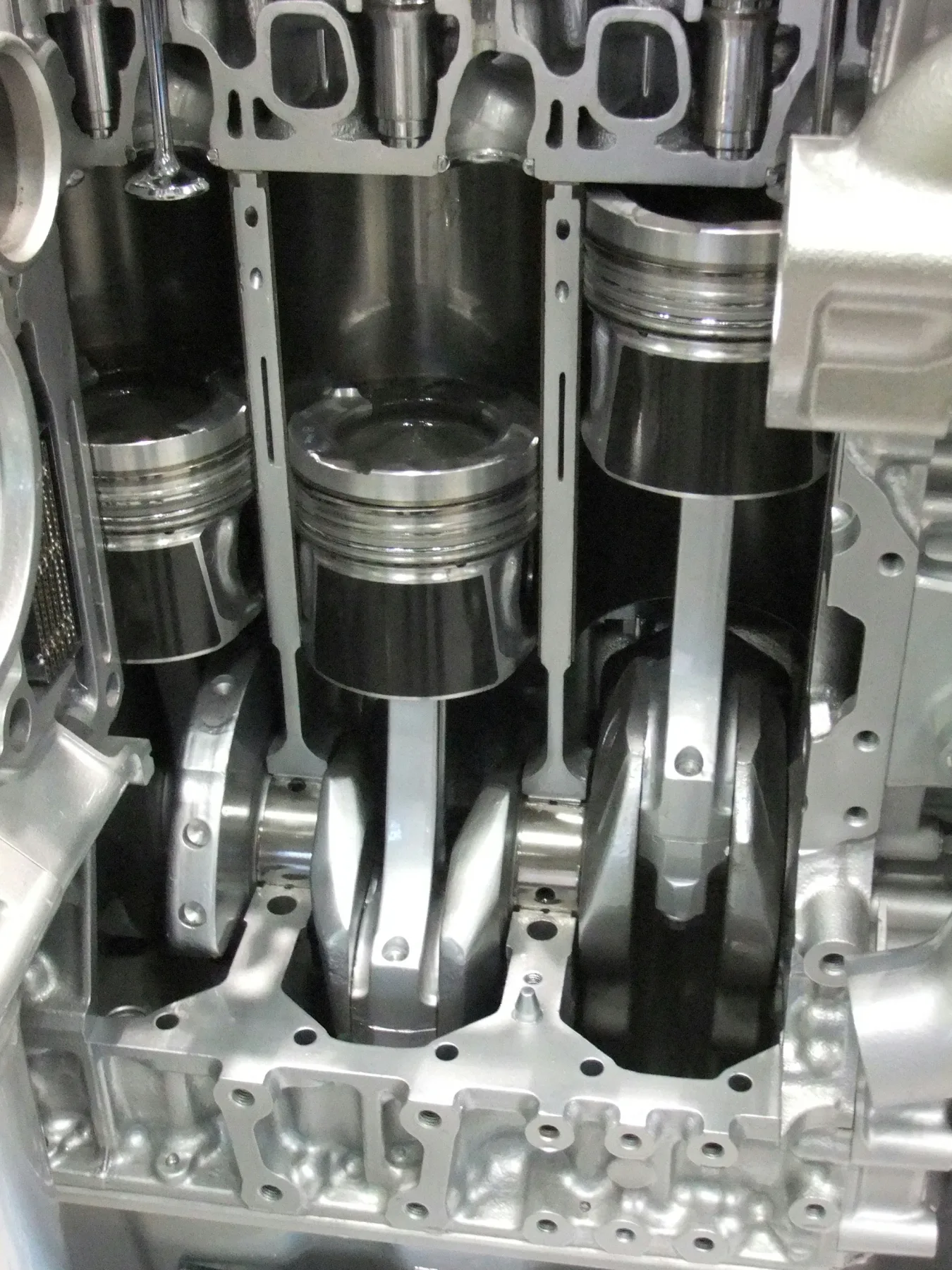

The cutaway is the geometry: piston, rod, and crank throw. It is not a reading of clearance or bolt tension.
Small end, then big end
The small end rides the piston pin. Shops also call that pin the wrist pin, and a bushing in the eye is common. Motorservice describes trapezoidal and stepped small ends where combustion load on the pin is higher. The big end is split so it can close around the rod journal. Two bearing inserts are the surface that runs on the crankpin. The rod and the journal are not meant to touch.
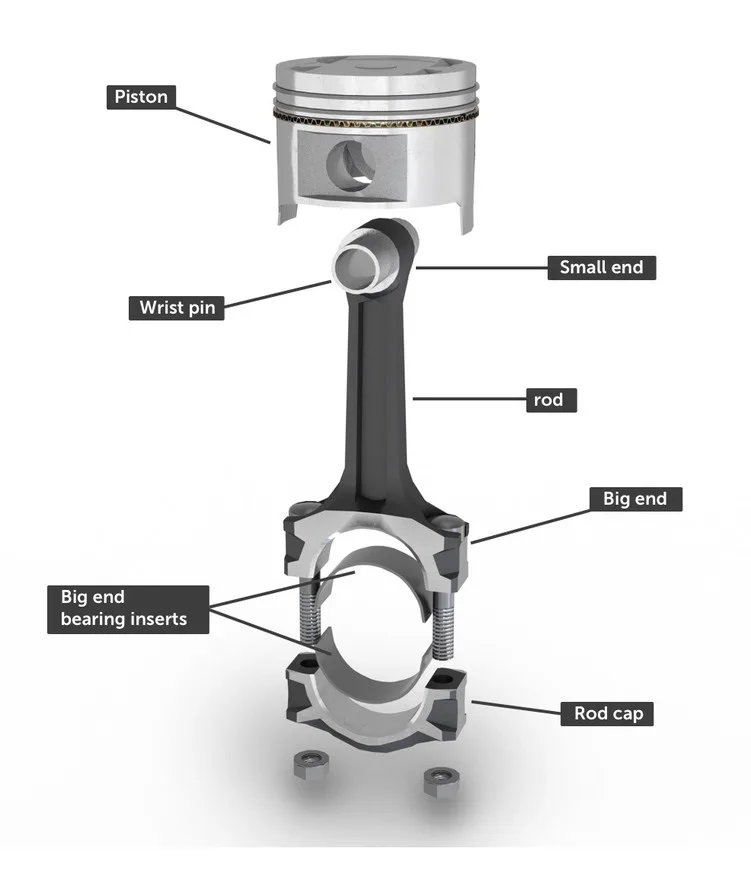

Bushing at the small end, inserts and cap bolts at the big end. A typical layout, not one engine’s print.
Clamp load, then crush
Over the top, inertia tries to pull the piston off the journal. The cap bolts clamp the big end shut. ARP’s design note treats preload as the tension that has to stay ahead of that pull. The bolt grows longer as the tension rises. Torque is a proxy, because friction in the threads and under the head uses part of the wrench effort. A photo of the beam does not show that stretch, and the value for a given bolt comes from the fastener maker.
The shells stay put by crush. MAHLE Clevite describes a half-shell slightly longer than half the bore. Drawn down, that extra length becomes the pressure holding the shell in the housing. A lug in a slot only locates it.
The same Motorservice range includes forged steel and sinter rods pressed from powdered metal. Cracked big ends, from break lines on sinter rods or laser notches on steel, leave a cap and beam that fit only as that pair.
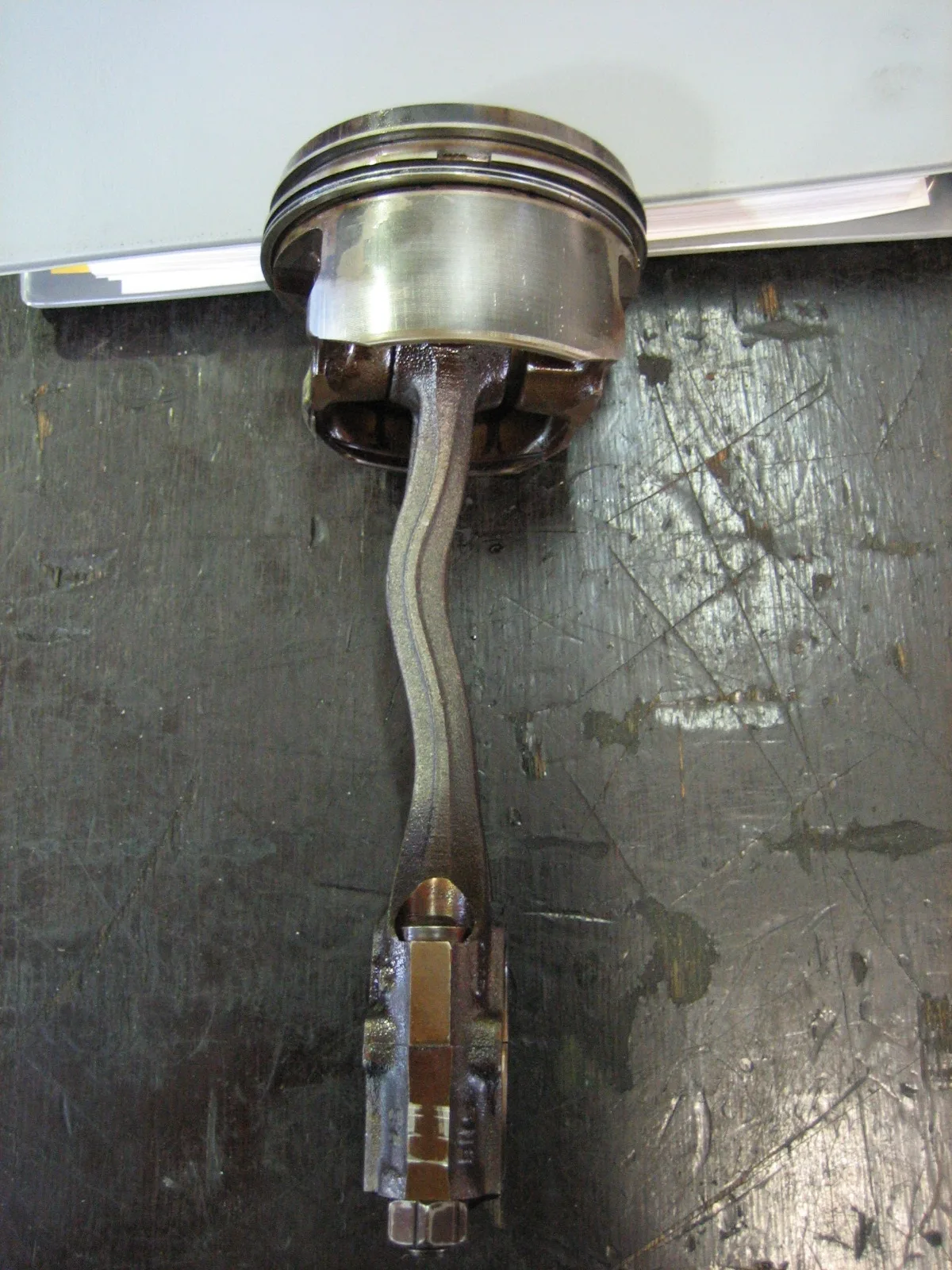

A bend is a shape
This shank no longer runs straight from the pin eye to the big end. The file description says hydrolock on a Seat Arosa rod. The frame shows neither the cylinder nor a valve, so the bend does not confirm it. MAHLE’s failure guide reads a bent or twisted rod from a cocked big-end bore and shell wear on opposite edges, which this photo does not include. Extreme running, a bad rebuild, or a dropped rod can each leave the same shape.
Sources
- Motorservice: connecting rods — Gas and inertia loads to the crankpin, forged steel, and sinter versus steel cracked big ends
- MAHLE Clevite TB-2072: bearing crush — Half-shell crush as the interference that holds a rod bearing in its housing
- ARP: connecting-rod bolt preload — Preload versus external load, and stretch as a reading of bolt tension
- MAHLE Clevite: bent or twisted connecting rod — Cocked big-end bore and bearing-edge wear, separate from a photograph of the shank
References checked .