Published by HALOX Co.
What a rack-and-pinion actually does
How a pinion slides a steering rack, how a recirculating-ball box swings a pitman arm, and where hydraulic pressure or an electric motor is added to each gear.
A steering shaft can arrive at either of two gears. In a rack-and-pinion, a pinion on the end of the shaft meshes with a long toothed bar, and the bar slides. In a recirculating-ball box, a worm turns inside a nut that rides on a circuit of balls, and the nut swings a sector and a pitman arm. The bar slides the tie rods sideways. The pitman arm swings a linkage.
TM 9-8000, the Army manual of 25 October 1985, with Change 1, describes the rack in paragraph 33-8. The pinion moves the rack left and right. Adjustable tie rods connect that rack to the steering arms and hold the toe angle. The joint itself, and the toe change that follows a change in length, belongs to the tie rod. The manual places this linkage on many smaller cars, and it limits the rack on larger vehicles to a conflict between the bar and the space the engine needs. That limit is the manual’s, written in 1985.
The mesh, and the nut on the balls
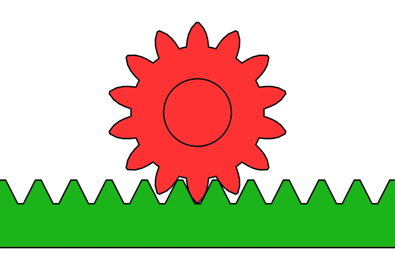

The drawing is the gear pair on its own: a pinion in mesh with a straight rack, the teeth one size along the bar. It is a study of that mesh, from no particular car.
Paragraph 33-7 is the other gear. The nut is a sleeve block mounted on a continuous row of balls on the worm, so the contact rolls. Tubular guides carry the balls diagonally back across the nut as it travels. Turning the worm moves the nut, and the nut turns the sector and the pitman arm shaft.
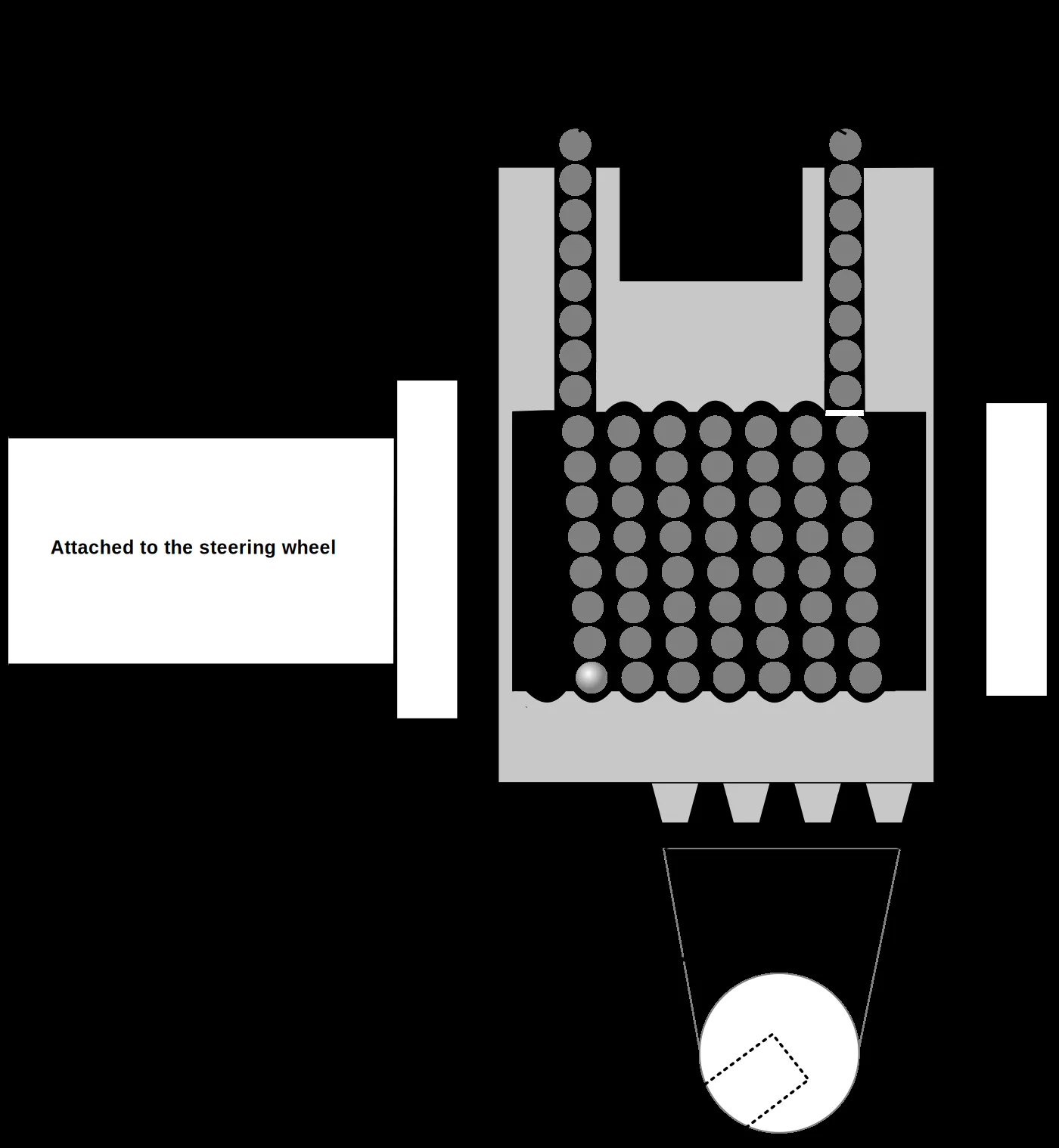

The drawing names a worm gear, recirculating ball bearings, a ball nut rack, a sector gear, and a pitman arm, and it marks the shaft as attached to the steering wheel. Commons describes the file as a modest-fidelity redrawing of an earlier diagram, so those labels are what the drawing commits to. Paragraph 33-7 has the nut turn the sector and the pitman arm shaft, and that paragraph does not call the nut’s teeth a rack. The long bar in paragraph 33-8 is the piece that slides.
Oil in the bar, oil in the box
A hydraulic rack keeps the pinion and the sliding bar, and adds a piston. ZF’s account of electrohydraulic steering pairs a motor-pump unit with a conventional rack-and-pinion. Pump pressure enters a steering cylinder that a separator piston divides into two chambers, one chamber for each direction of assist. The pinion has helical teeth. Turning the wheel moves the rack and the rods axially, and the track rods and stub axles take that slide out to the wheels. The motor-pump unit supplies a higher pressure for parking, low speed and a large steering angle, than it does in a straight line at high speed. The pump that makes the flow is a separate part, covered in what a power steering pump actually does.
The integral power gearbox in the same Army chapter starts from a manual box and builds the assist into that box. The offset type is a recirculating-ball gearbox. Its piston sits offset from the worm and nut and is attached to a rack meshed with the pitman sector. The in-line type seals the ball nut inside a cylindrical part of the housing and uses the nut itself as the piston, pressurizing one side and then the other. The control valve, moved by the steering wheel, can sit in the box or on the linkage. With no steering force the spool stays centered and the oil returns to the reservoir. A turn shifts the spool, opens a passage to one side of the piston, and opens the return for the fluid the piston displaces. The rack in that offset box is the toothed piece on the piston side of the sector. It is the box’s rack, the piece that turns an arm, and the long sliding bar is a different part.
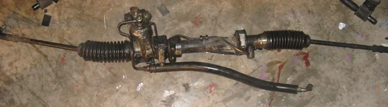

The photograph is a hydraulic rack off the vehicle: a long housing, rubber boots, inner tie rods leaving the boots, and hydraulic lines on the housing. Commons titles it a hydraulic power steering rack with rubber boots and inner tie rods. The picture carries no vehicle name, no pressure, and no chamber.
Where the motor is bolted
JTEKT’s engineering journal, English edition No. 1006E (2009), sorts electric power steering by where the assist sits. Column assist increases the load on the intermediate shaft, the rack and pinion, and the reduction gear. Pinion assist increases the load on the rack and pinion and the reduction gear. Rack assist increases the load on the reduction gear. The journal calls rack assist the more advantageous of the three for high-powered use, because the extra load stays on the reduction gear. The rack-direct system it then describes is one form of that rack assist: a ball-screw reduction and a brushless motor on the same axis as the rack.
Bosch publishes the split as separate units. The column unit, for small and mid-size vehicles, puts the motor and its electronics in the steering column. Sensors and a torsion bar sit next to a helical gear. A worm gear turns the motor’s torque into assist on the steering shaft, and an intermediate shaft joins that column to a mechanical rack and pinion. Bosch prints the assist as 100 Nm of output torque.
On the single-pinion unit the driver’s torque and the servo’s torque reach the rack through one pinion. The motor drives that pinion through a worm gear. Bosch prints 13 kN of rack force. The column figure is torque at the column unit. The single-pinion figure is force at the rack.
The dual-pinion unit separates the servo from the sensor. The motor’s worm gear produces a servo torque and transfers it to the rack, and the page lists variable steering ratio for driving dynamics. Rack force on that page is also 13 kN. Nexteer’s pinion-assist page draws the same line from the other side: single-pinion assist is built into the primary pinion shaft, and the dual-pinion layout leaves the primary pinion for the steering geometry and uses a second pinion for the assist, with room to place the motor on the side of the engine bay opposite the driver.
The belt-drive unit is where recirculating balls show up on a rack. Driver torque still reaches the rack through a pinion. The motor turns a toothed disc, a belt takes that torque to the servo gear, and a ball screw turns the motor’s rotation into the rack’s slide. The balls return through a channel in the nut. Bosch prints 25 kN of rack force, lists a variable steering ratio, and describes a standard version for mid-size cars, sports cars, SUVs, and light commercial vehicles, plus a high-load version for heavy SUVs, transporters, and pickups. Those balls push the rack along its housing. The balls in paragraph 33-7 move a sector and a pitman arm.
Nexteer’s rack-assist page puts the electronics on the rack housing, for the heat and the exposure of an engine compartment, and it describes that layout from mid-size vehicles through full-size trucks. The 1985 manual’s space limit and this rack-mounted assist are two statements, written decades apart, about where a long bar fits.
A ratio, and a motor that adds rotation
On the worm-and-roller gear in paragraph 33-5, the manual defines a variable ratio as a ratio that is larger in one position than in another, so the road wheels turn faster in some positions than in others. At the straight-ahead position the ratio is high, which the manual ties to more steering control. As the wheels are turned toward lock, the ratio falls and the action becomes more rapid. The hourglass form of the worm is what that paragraph uses. The definition belongs to that gear.
Bosch lists driving dynamics via a variable steering ratio on the dual-pinion unit and again on the belt-drive unit. Those listings give no on-center ratio, no off-center ratio, and no tooth module. The journal’s E-VGR is a further machine, on the rack-direct gear that paper develops. It varies the front-wheel angle relative to the steering-wheel angle by adding rotation through a motor and a reduction gear. In the earlier layout the whole mechanism turned with the intermediate shaft, and a spiral cable fed it. In the system the journal describes, the unit sits on the upper part of the pinion, the output shaft passes through a hollow motor shaft, and the spiral cable is gone. That added rotation is the ratio change JTEKT is describing. The hourglass worm is a different part, and the Bosch pages do not tie their variable-ratio line to either mechanism.
Bellows, clamps, and the inspection
Bosch’s workshop sheet for electric steering systems and the sheet for hydraulic systems, both marked 2024/11, treat the bellows as an attachment part. A bellows or a tie rod can be damaged or worn, and the sheets say to replace that part. A complete steering system, on the same sheets, is usually replaced after an accident or a mechanical overload that affects the steering function. The sheets want the bellows, the tie rods, and the clamps to be the ones the manufacturer approves, installed so the consequence they name, corrosion, is avoided. The first step they require is a visual and functional inspection: operating forces, the way the steering returns, clearances, noises, and the warning lamp. An in-depth diagnosis follows, and that is what decides whether the system is replaced or repaired.
The boots in the photograph are closed over the inner rods. The photograph records none of the forces, the return, the clearances, the noises, or the lamp. The inner joint under a boot, and the toe change that follows a length adjustment, stay with the tie rod. The gear’s job is the conversion: a pinion and a sliding bar, or a worm, a circuit of balls, a sector, and an arm, with the oil or the motor added at the place that unit was built for.
Sources
- Department of the Army: TM 9-8000 — Chapter 33 of the 25 October 1985 manual, with Change 1: the rack and pinion in paragraph 33-8, the recirculating-ball worm and nut in 33-7, variable ratio on the worm-and-roller gear in 33-5, and the control valve and integral power gearbox in 33-10 and 33-11
- ZF Aftermarket: function principle of electro-hydraulic power steering — TRW electrohydraulic steering as a motor-pump unit plus a conventional rack-and-pinion, the separator piston and two cylinder chambers, speed- and angle-dependent pressure, and axial rack movement through a helical pinion
- Bosch: electric power steering with servo unit on the steering column — EPSc for small and mid-size vehicles: motor and electronics in the column, worm gear to the steering shaft, intermediate shaft to a mechanical rack and pinion, and 100 Nm of output assist torque
- Bosch: electric power steering with single pinion servo unit — EPSp: driver torque and servo torque through one pinion, worm gear from the motor to that pinion, and 13 kN of steering rack force
- Bosch: electric power steering with servo unit on a second pinion — EPSdp: servo separated from the sensor unit, worm gear into servo torque transferred to the rack, 13 kN of rack force, and variable steering ratio listed for driving dynamics
- Bosch: electric power steering with belt drive servo unit — EPSapa: driver torque through a pinion, motor torque through a toothed belt and a recirculating-ball screw to the rack, 25 kN of rack force, variable steering ratio, and the standard and high-load vehicle classes
- JTEKT Engineering Journal No. 1006E — English edition, 2009: column, pinion, and rack assist, the load each one puts on the shaft and the gear, rack-direct EPS with a ball screw and a coaxial motor, and E-VGR adding rotation at the pinion
- Nexteer: single and dual pinion-assist EPS — Assist on the primary pinion shaft, and a second pinion used for assist so the primary pinion can be laid out for the steering geometry
- Nexteer: rack-assist electric power steering — Electronics on the rack housing, and the layout described for mid-size vehicles through full-size trucks
- Bosch: replacement of electric steering systems — Workshop sheet marked 2024/11: bellows and tie rods as attachment parts, when a complete electric system is usually replaced, installation against corrosion, and the inspection that comes first
- Bosch: replacement of hydraulic steering systems — Workshop sheet marked 2024/11: the same split between bellows and a complete hydraulic system, approved clamps, and the inspection of forces, return, clearances, noises, and the warning lamp
References checked .