Published by HALOX Co.
What a torque converter actually does
The impeller, turbine and stator in a torque converter, torque multiplication, and why modern lock-up clutches can operate before steady cruise.
A torque converter couples an engine to a conventional automatic transmission using moving fluid. Its impeller turns with the engine and drives fluid toward a turbine connected to the transmission input. The two can turn at different speeds, so the engine can keep idling while the vehicle is held stationary in Drive.
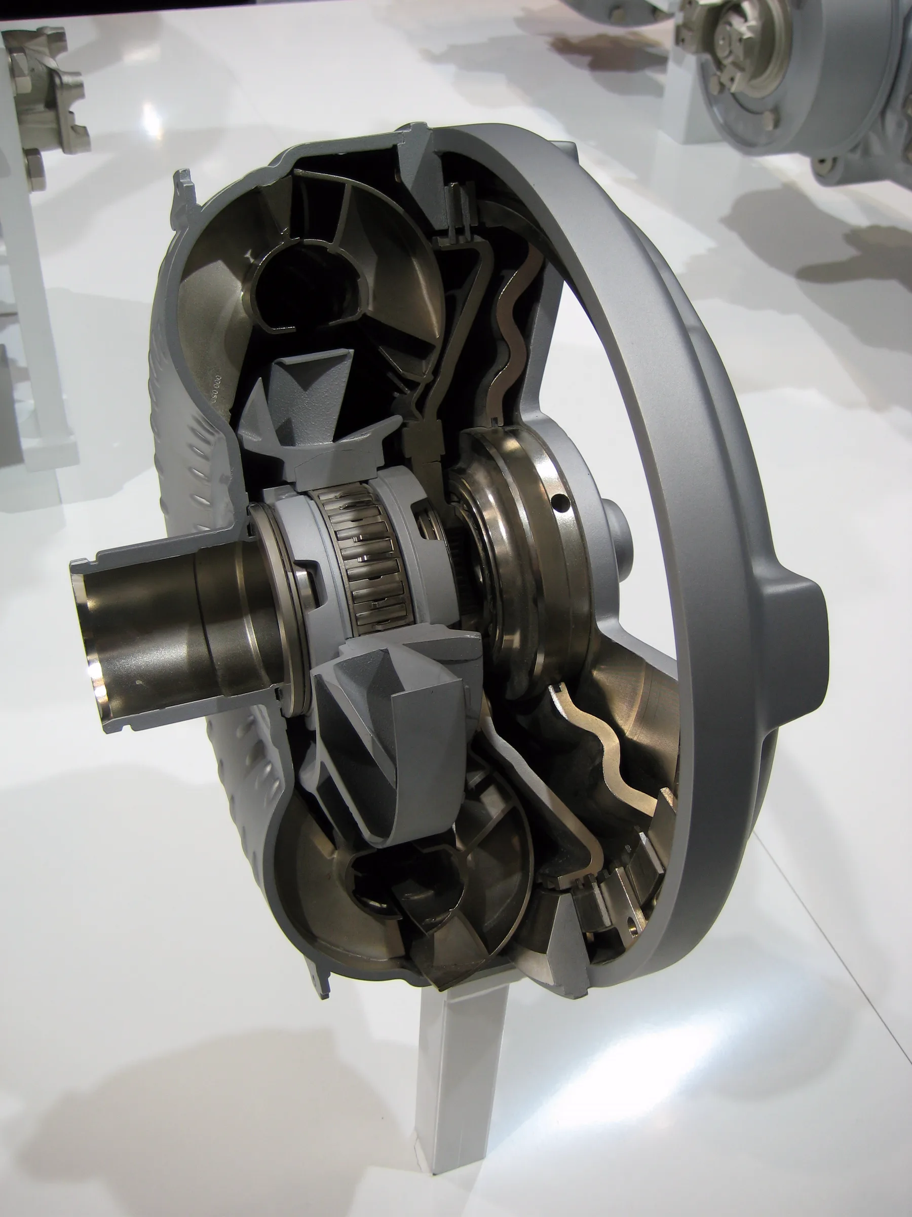

That is the converter’s fluid mode. It does not mean the transmission has no clutches: the gearbox uses its own clutches, and many converters also contain a lock-up clutch. The cutaway shows one converter’s construction; dimensions and internal damping arrangements vary by application.

The stator changes the return flow
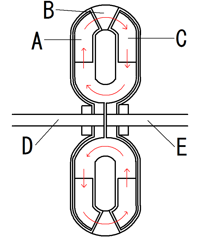
A simple fluid coupling has an impeller and turbine. A torque converter adds a stator to redirect fluid returning from the turbine toward the impeller. That reaction allows torque multiplication while the turbine turns substantially slower than the impeller. AmTech, a stator supplier, describes the three elements and return-flow role.
Multiplication does not create extra power: increased output torque comes with a lower output speed and losses to heat. As the input and output speeds approach each other, the converter moves toward its coupling condition. The stator’s support and one-way-clutch arrangement depend on the converter design.

Lock-up need not wait for cruise
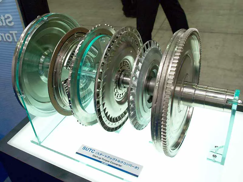
The lock-up clutch provides a mechanical torque path between the engine-driven cover and the turbine side, reducing fluid slip. Transmission control can apply, release or modulate it according to load, speed and the design’s vibration limits. It is not universally reserved for steady highway speed. ZF describes modern converters that permit early lock-up.
A shudder while rolling does not prove that this clutch has failed. Fluid condition, engine operation and transmission control can produce overlapping symptoms. The useful distinction is the torque path: moving fluid during converter operation, with a friction clutch adding a mechanical path when commanded.
Sources
- AmTech OEM: torque converter stator — Impeller, turbine, stator and return-flow redirection
- ZF: torque converter — Lock-up clutch, vibration damping and early application
References checked .