Published by HALOX Co.
What a universal joint actually does
How a cross-and-bearing universal joint carries torque across an angle, why one Cardan joint changes shaft speed, and what a vibration or a loose joint does and does not prove.
Torque comes off the transmission, or off the transfer case, on an end yoke. From there a Cardan joint has to turn a shaft that is not in line with that yoke. Neapco calls this a non-constant-velocity joint: two yokes connected by a cross through four bearings. The cross is the drive member, four trunnions in one plane, and each trunnion sits in a bearing cup. In that glossary a round bearing is the cup with needle rollers riding the trunnion. Spicer’s Life Series cups use flat-ended needles for the oscillating load while the shaft turns, and thrust washers against end galling on the trunnion ends. One pair of cups is held in the driving yoke. The cross carries the torque across to the other pair, and the second yoke takes it onward.
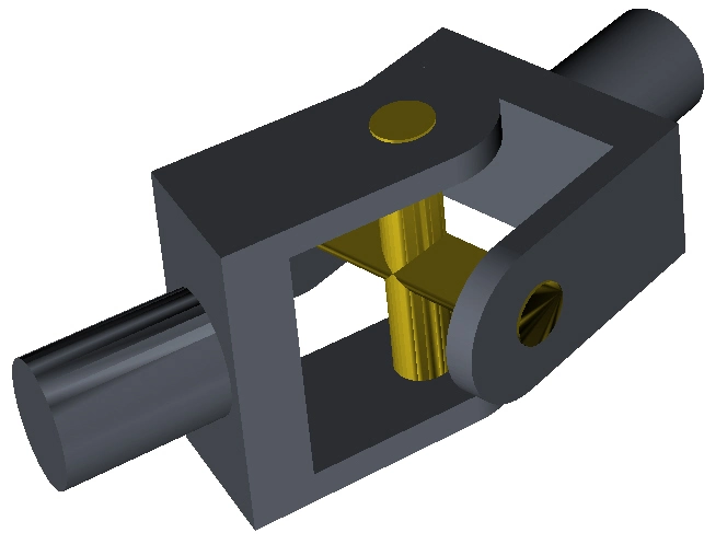

One cup is off its trunnion, which is where those needle rollers run. The other cups are still on the cross.
On a rear-drive shaft the second joint faces the other way and hands the torque to the pinion yoke at the differential. The tube between the joints has to change length, because the axle moves as the suspension works. TM 9-8000 puts the slip splines at the transmission or transfer-case end: a male spline on the shaft and a female spline fixed to the joint, so the shaft can telescope and still turn. Spicer’s installation manual treats the angle at each joint as its own source of vibration. That angle is what you have when the transmission output, the driveshaft, and the axle input are not in one line.
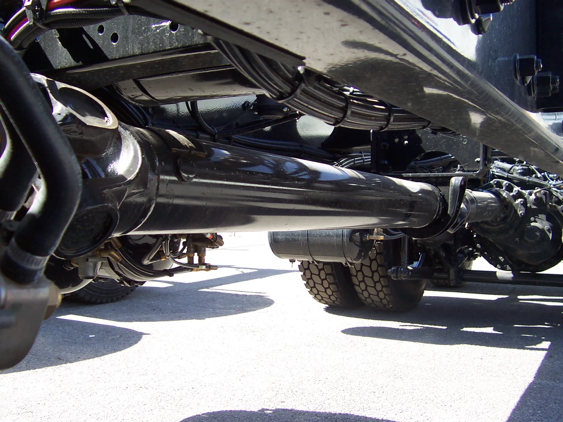

A truck propeller shaft, a joint at each end of the tube and a center support along it. The frame shows the parts. It does not show the operating angles, and it does not show whether the yokes are in phase.
Twice in one turn
A single conventional joint does not hold the driving shaft’s speed once the two shafts meet at an angle. TM 9-8000 plots one revolution with the driving shaft held at 1,000 rpm and the shafts 30 degrees apart. Through a quarter of that turn the driven shaft runs from 866 rpm to 1,155 rpm. The two speeds match only at 45, 135, 225, and 315 degrees, so the speed rises and falls twice per revolution. The manual puts the size of that swing at roughly 7 percent for a 15-degree angle and about 30 percent for 30 degrees. Those figures are the plotted cases. Spicer’s installation rules keep a working driveshaft much closer to straight: at least 1 degree at each end, the two ends equal within 1 degree (within half a degree on a motor home, or on a shaft in front of a transfer case or an auxiliary device), and 3 degrees or less where the aim is a driveline essentially free of angle vibration. Past 3 degrees, that manual says, joint life drops and a vibration can show up. Its chart of maximum angles runs from 3.2 degrees at 5,000 rpm to 11.5 degrees at 1,500 rpm. Neapco’s general note calls 0.5 to 3 degrees good practice, asks that the two joints on one shaft stay within 1 degree of each other, and allows a higher angle depending on shaft speed.
The speed change comes from the way the cross is allowed to move. The Army manual says the journal that joins the yokes can only pivot, so as the joint rotates the journal tilts back and forth. Tilt toward the output shaft adds to that shaft’s speed, and tilt away from it subtracts. The two speeds match only while the journal lies in the plane that bisects the angle between the shafts, which is four times in a revolution.
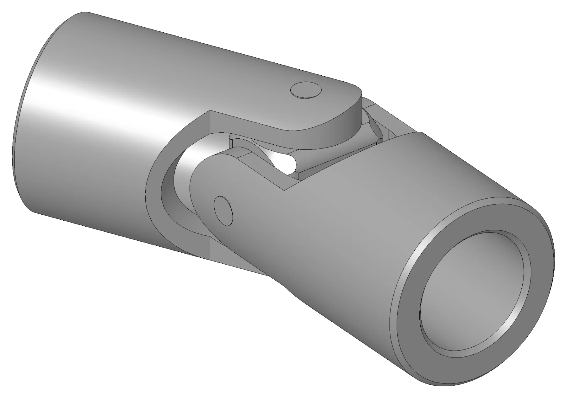

Two yokes and the cross between them. A drawing of a single Cardan joint, not a vehicle driveshaft, and not the 30-degree case in the speed plot.
A second joint, phased
The speed change is taken out with a second joint. TM 9-8000 puts that joint on the other end of the propeller shaft and sets two conditions. The angle between the transmission shaft and the propeller shaft has to match the angle between the propeller shaft and the rear axle’s final drive, and the two yokes on the propeller shaft have to lie in the same plane. The first joint is then at its largest speed change at the moment the second is at its smallest, and wheel speed holds steady for a given engine speed. The shaft between the joints is still changing speed the whole time. Spicer’s installation manual states that cancellation as equal operating angles, within 1 degree, on a shaft whose inboard yokes are in line. That in-line position is what the manual calls phased. Neapco’s build procedure holds the cross holes of a two-joint shaft in line within 2 degrees. Spicer’s service manual says putting the driveline back together out of its original phase can cause vibration and failure of the shaft and the parts it is bolted to.
A double Cardan is the arrangement for an angle a single joint is not meant to carry. Neapco defines it as two Cardan joints whose yokes are connected by a coupling yoke, or H-yoke, with an internal support that centers them, and calls the result near constant velocity. The usual application in that guide is the front shaft of a 4x4. TM 9-8000’s double cross-and-roller is two cross-and-roller joints linked by a centering yoke and a spring-loaded centering ball. The manual says that ball and yoke split the drive angle equally and hold a constant drive velocity. The ball-type joint at a steered front wheel is a separate part. At steer angles up around 30 degrees, the same manual says a conventional joint would make the steering heavy and would slip and wear the tires, so a constant-velocity joint connects the front axle shaft to the wheel. That joint is the one in what a CV joint actually does. Spicer’s crosses also turn up on steering shafts. The 1000-series steering-shaft parts list says the pieces to replace on those shafts are the end yokes and the U-joint kits, and that the shaft number itself has to come from the vehicle maker.
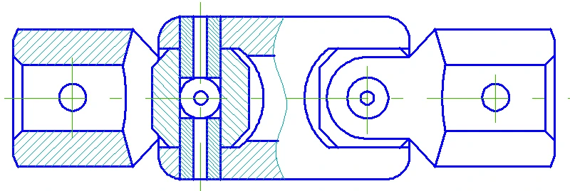

Two crosses, the center yoke, and the centering ball. The picture does not show the angle the joint is running, and it does not show a spring on the ball.
What a sign can settle
Spicer’s installation manual names four signs of a joint on its way out: a vibration the driver is told to report, looseness measured as end play across the bearings, discoloration from heat, and a joint that will not purge all four trunnion seals when it is greased. Most of the failures in that account trace to the lubricating film, from missing lubricant, from lubricant that was wrong for the job, or from lubrication that was late or incomplete. The failures outside that group are tied to installation, to angles and speeds, or to manufacturing discrepancies. Vibration is also how that manual opens its list of ordinary driveshaft trouble, and the three most common causes there are imbalance, critical speed, and the operating angles. Neapco’s chart for the same complaint adds a joint that is already defective, a shaft outside straightness and balance, a worn slip assembly, and a tube too long for the speed. A shake under the floor picks none of those by itself.
Looseness is a measurement, and grease can hide it. Spicer’s service procedure is done before the joint or the slip member is lubricated, because fresh grease can mask play that is already there. On the shafts that procedure covers, the inboard yoke should move less than 0.006 inch (0.15 mm) relative to the joint, checked vertically and horizontally. Past that, the kit may need to be replaced. The carrier’s input-shaft and output-shaft end play has to be inside specification first. If it is not, the manual says to correct it before the joint reading can be trusted. Heat color, and a seal that will not pass grease, are things the installation manual says to look for when the joint is relubed. They are findings on the joint. They do not name which of the film, the angle, or the installation left them.
Sources
- Spicer: driveline installation J3311-1-DSSP — Angle vibration, equal operating angles, in-line inboard yokes, and signs that are not one diagnosis
- Spicer: driveshaft service manual DSSM-0100 — Needle bearings, reassembly phase, and the looseness check before grease
- Neapco: driveline general information — Cardan and double-Cardan construction, 4x4 front shafts, phasing, and vibration causes
- Department of the Army: TM 9-8000 — Why one conventional joint changes speed twice a revolution, and how a second joint cancels it
- Spicer: 1000-series steering shafts — End yokes and U-joint kits as the replaceable pieces on those steering shafts
References checked .