Published by HALOX Co.
What a wheel speed sensor actually does
How ABS reads wheel rotation, how a passive inductive sensor differs from a powered Hall, AMR, or GMR sensor, and what an ABS or stability lamp establishes.
The ABS light stayed on. Is the wheel speed sensor the part that failed?
The lamp is a condition in the system. The part is a later question. Standard No. 135, Light vehicle brake systems, in the 2025 Code of Federal Regulations, defines an antilock brake system as the portion of the service brakes that automatically controls rotational wheel slip while braking. It does that in three steps. It senses the rate of angular rotation of the wheels. It transmits signals about that rate to one or more controlling devices. Those devices send controlling signals to one or more modulators, which adjust the brake actuating forces. The same standard requires a warning indicator for any electrical functional failure in the antilock system, and it requires the indicators to light as a check when the ignition is turned on and the engine is not running. The failed-antilock test creates the failure by disconnecting the functional power source, or any other electrical connector that produces a functional failure. On the 2024 Camry quick reference guide, for the Camry, the Camry AWD, and the Camry Hybrid, the guide says it is a summary and points to the owner’s manual in the glove box. The ABS warning there carries one note. If the indicator does not turn off within a few seconds of starting the vehicle, there may be a malfunction, and a Toyota dealer inspects the car. The standard’s condition is an electrical functional failure. The Camry note says there may be a malfunction. The sensor, the ring, and the module are outside both sentences.
The ring in front of the sensor
The sensor is aimed at a target that turns with the wheel. The target is not one shape.
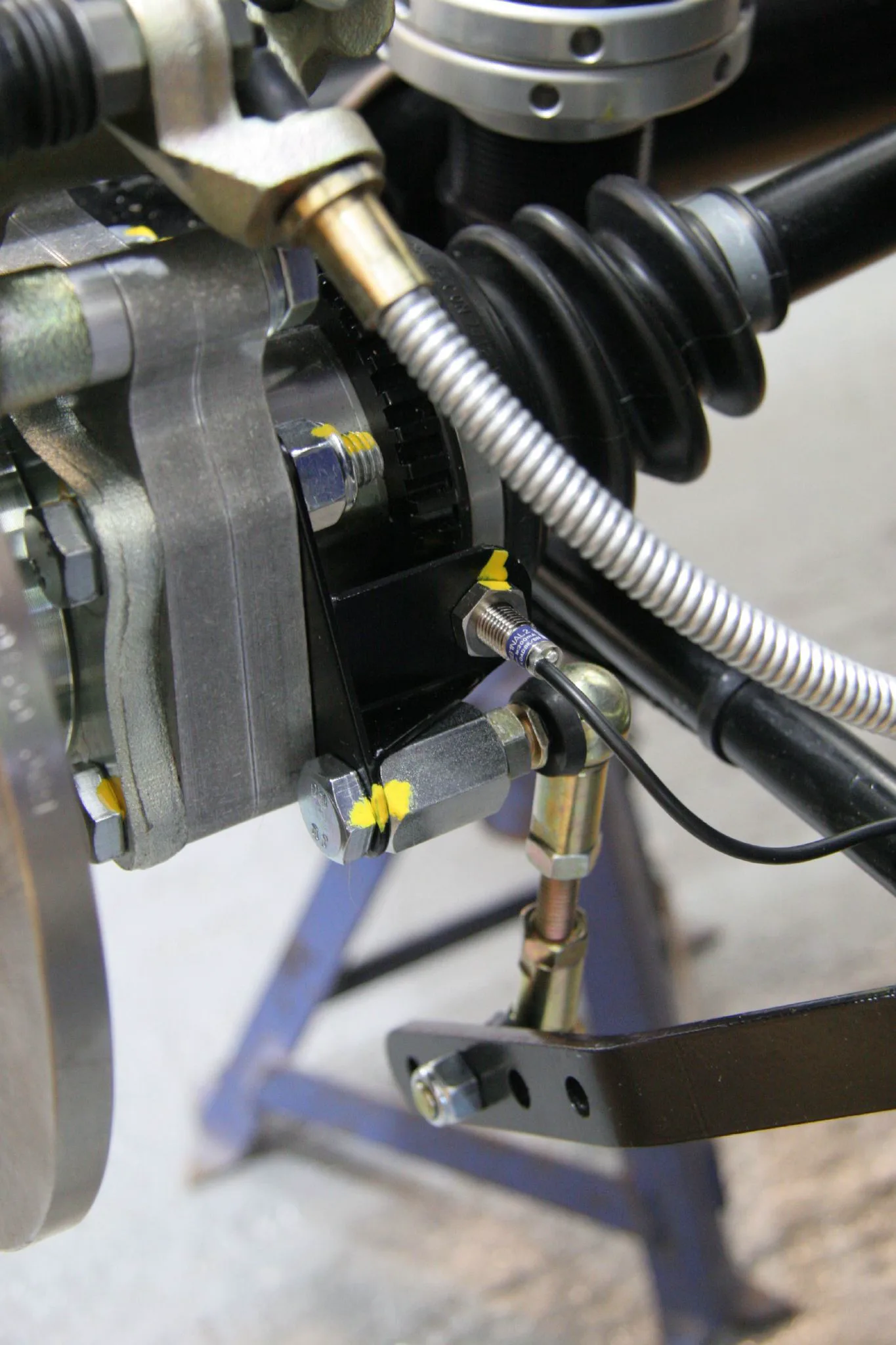

The file identifies this as a speed sensor and its bracket on a Caterham Roadsport during assembly. The corner sits on a blue stand over a concrete floor. A ribbed black rubber boot and a black suspension arm sit behind a gray upright, with the edge of a brake disc at the left. A dark toothed ring shows behind the upright. A black bracket sits next to the teeth, and a small metal sensor with a black wire faces the ring. A braided hose crosses above the ring. Yellow paint marks several bolts. A blue stand is under the corner. HELLA’s page on wheel-speed sensors puts a passive sensor directly above an impulse wheel connected to the wheel hub or the drive shaft. The gap between the sensor and that wheel is set by the axle design.
The teeth can also sit on a joint that has come out of the car.
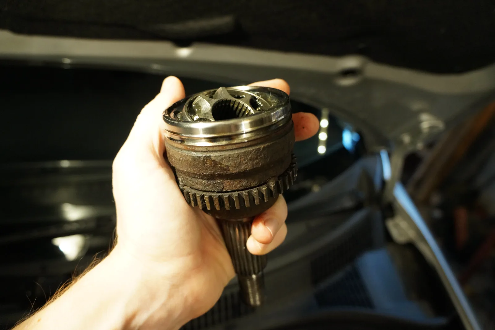

A hand holds a rusty metal joint over an open engine bay. A ring of teeth circles the joint. A splined shaft points down, and the open end shows internal splines. The hood opening and a dark compartment are behind the hand. The file page calls that ring a broken ABS tone ring on a CV joint; the break itself is not visible from this side.
The other target is a ring of magnets. HELLA describes a multipole ring used as the impulse wheel and built into the sealing ring of a wheel bearing, with magnets laid in alternating poles. Bosch’s wheel-speed sensor page says the encoder its circuit faces is either a multipole or a steel wheel, and that a steel wheel needs a magnet placed inside the sensor. NXP’s KMI25 datasheet is an anisotropic-magnetoresistive sensor dedicated to ABS, split the same way. The KMI25/2 is for a magnetized multipole encoder. The KMI25/4 is for a ferromagnetic gear wheel. Infineon’s TLE5045iC is the encoder case. The datasheet describes a giant-magnetoresistive element facing a magnetized encoder wheel, and this part has no direction output.
A voltage the wheel makes, or pulses the module powers
HELLA says a sharp line between active and passive has not been defined, and then gives the split it uses in the workshop. A passive sensor operates with no supply voltage applied. An active sensor is supplied, and then it generates an output.
On the inductive passive sensor, a pole pin inside a winding meets a permanent magnet, and the magnet’s field reaches the toothed wheel. As the wheel turns from a tooth to a gap, the field through the winding changes, and that change induces an alternating voltage in the winding. The frequency and the amplitude of that voltage are both related to wheel speed. The control unit has a voltage range it will accept. The sensor takes no separate supply from the control unit.
The active sensor is a proximity sensor with its electronics inside, supplied with a defined voltage from the ABS control unit. HELLA’s magneto-resistive version reads the alternating field of the multipole ring, turns the sinusoidal signal into a digital signal, and sends it as a current using pulse-width modulation. The cable has two wires. The signal rides the supply wire, and the other wire is the sensor ground. Where the car has a steel impulse wheel instead of a multipole ring, a magnet is fixed on the sensor element, and the processing is the same. HELLA credits the active sensor with wheel speed from a standstill, down to 0.1 km/h, and says that reading matters to traction control as soon as the vehicle pulls away. The Hall sensors on that page detect forward and backward movement.
Bosch publishes its wheel-speed sensor as an active Hall circuit. The Hall element, the amplifier, and the signal processing sit on one chip, sealed in the sensor head. The element produces an alternating voltage proportional to the changing field, and the circuit delivers current pulses whose frequency is proportional to wheel speed. Bosch states detection of very low speed nearly to a standstill, 0.1 km/h, on a two-wire current interface. The page lists the sensor with the antilock braking system, and it calls wheel-speed sensors part of brake-control and driving-management systems.
NXP puts the speed information on the supply current. The KMI25 outputs a pulse at each zero-crossing of the magnetic signal, so the pulses come at twice the frequency of the field, which is how the datasheet measures the encoder’s rotational speed. The signal chain still works when the field is steady. The datasheet calls that true zero-hertz capability, and it reads direction from the phase between the two halves of the bridge. Allegro’s A19200 is a Hall-effect wheel-speed IC for two-wire use, described as true zero-speed ring-magnet sensing. In the sensing section, two Hall elements read the magnetic profile of a ring magnet or a gear target. Infineon states the TLE5045iC output as a two-wire current, 7 mA and 14 mA. The operating range for the magnetic-signal frequency begins at 0.03 Hz. The datasheet ties that switching accuracy to indirect tire-pressure monitoring: the speed is sensed accurately enough for the sensor to be used as a component of that system. This part does not report direction.
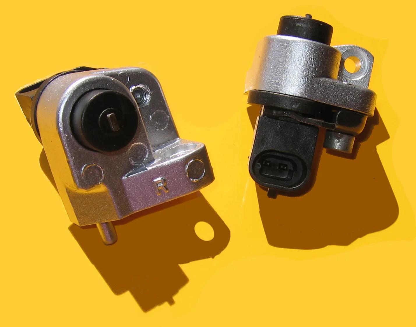

The file identifies these as GM ABS sensors. They sit on a yellow background. The left one is a silver bracket with a black round cap, a short metal pin at the bottom, and a stamped R. The right one is a silver body with a black connector that shows two metal contacts. No other lettering is readable. HELLA says active and passive sensors cannot always be distinguished by appearance, and that the maker’s specification is what sorts them. The same note says manufacturers have mainly installed active wheel sensors since 1998. The photograph is two housings.
What receives the pulses
Standard No. 135 stops at the architecture. A controlling device interprets the rotation signals, and modulators adjust the brake force.
Bosch’s ABS description names the hardware. The hydraulic unit is the central component. It includes valves that control braking pressure at each wheel, a return pump, and an electronic control unit. Each of the four wheels has a wheel-speed sensor. The sensors measure that wheel’s speed and transmit it to the control unit. If a wheel is about to lock under heavy braking, the system reduces the braking pressure on that wheel until the threat of locking has passed, then increases the pressure once the wheel turns freely. The cycle continues until the driver reduces the force on the pedal, or until the tendency to lock is gone, for instance because there is more grip. Depending on the system, the brake pedal may pulsate.
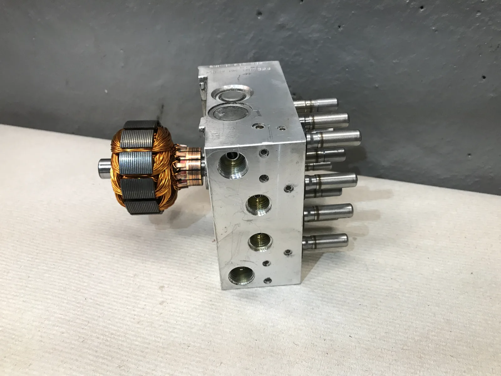

The file calls this an ABS hydraulic control unit. An aluminum block sits on a white cloth against a gray wall. Copper-colored wire is wound around a core with dark segments at one end. Round ports are machined into the face, and rows of smooth round metal stems project from the side. Marks on the top of the block are not readable.
Stability control, on Bosch’s ESP page, includes the functions of ABS and of the traction control system. Speed sensors on each wheel measure wheel speed. From the steering angle, the system takes the direction the driver is asking for. Yaw-rate sensors measure rotation about the vehicle’s vertical axis, and lateral acceleration. The control unit calculates the actual movement from that data and compares it with the intended direction 25 times a second. When the two do not correspond, the system reduces engine power. If that is not enough, it brakes individual wheels.
Standard No. 126, Electronic stability control systems for light vehicles, in the same 2025 Code, requires a system that applies and adjusts brake torques individually to produce a correcting yaw moment, with closed-loop control that limits oversteer and understeer. The system has a means to determine yaw rate and to estimate sideslip, a means to monitor driver steering, and a means to modify engine torque. It has to apply brake torque individually at all four wheels, and it has to remain capable of activation when the antilock system or traction control is also activated. The wheel-speed sensors in that comparison are on Bosch’s ESP page. The standard’s required equipment is the brake torques, the yaw rate, the sideslip estimate, the steering input, and the engine torque.
HELLA says the ABS control unit also provides the wheel-speed information to other systems over data lines, and it names the engine, the transmission, navigation, and chassis control. The indirect tire-pressure use is the one the TLE5045iC datasheet states for that sensor. The Camry guide describes that car’s anti-lock system as detecting which wheels are locking and limiting lockup by pulsing each wheel’s brakes independently. Its traction control, when a drive wheel starts to slip, limits engine output and applies brake force to the spinning wheel. The guide sends the reader to the owner’s manual for the limitations. It does not name the sensor those functions read.
What the lamp settles
Standard No. 135 activates an indicator when the ignition is on and any electrical functional failure exists in an antilock system or a variable brake-proportioning system. A functional failure, in the definitions, is a failure of an electrical or mechanical component that leaves the system totally or partly inoperative while the structure of the system stays intact. The indicator line for the antilock system is the electrical case. An indicator that comes on for one of the listed conditions stays on as long as the condition exists, with the ignition on, whether or not the engine is running. The same indicators come on as a check, automatically when the ignition is turned on with the engine not running, or by a single manual action. If the antilock condition has its own indicator, the letters and the background are contrasting colors, one of them yellow, and the label is Antilock, Anti-lock, or ABS. A vehicle with a split service brake system may use one common indicator, displaying the word Brake, for two or more of the warning conditions.
The failed-antilock procedure disconnects the power source or another electrical connector, checks that the indicator comes on, and still requires the service brakes to operate and to stop the vehicle as that section specifies. From 100 km/h, under the test conditions written there, the stopping distance is 85 meters (279 feet) or less. The same test allows no wheel to stay locked for more than 0.1 seconds above 15 km/h. The lamp is the indicator the standard requires for the electrical failure. The disconnected connector is one way the standard produces that failure. The stop, with that lockup limit, is the requirement that remains.
Standard No. 126 requires an ESC malfunction telltale for malfunctions that affect the generation or transmission of control or response signals in the ESC system. Aside from the exceptions in that section, the telltale illuminates when a malfunction exists and stays illuminated, with the ignition on, for as long as the malfunction exists. It is also activated as a bulb check when the ignition is turned on with the engine not running. It has to go out at the next ignition cycle after the malfunction has been corrected. The manufacturer may flash the telltale to indicate that ESC is operating. The manufacturer may also hold it steady for malfunctions of related functions that share components with ESC. The standard names traction control, trailer stability assist, corner brake control, and similar functions that use throttle or individual wheel torque. A separate ESC Off telltale covers a mode that leaves the system unable to meet the performance requirements. That telltale is the mode. The malfunction telltale is the fault.
On the Camry guide the ABS warning carries the note about an indicator that is still on a few seconds after starting. The slip indicator carries that note and a second one: if the indicator flashes, the system is operating. The guide lists the brake-system warning as its own symbol. HELLA includes the ABS warning light among the characteristics that can show up when wheel-speed sensors fail, with a stored fault code, wheels locking during braking, incorrect regulation, and the failure of further systems. The causes on the next list are a break in the wiring, an internal short, external damage, heavy contamination, increased wheel-bearing clearance, and mechanical damage to the encoder wheel. The troubleshooting section starts from a malfunction of the ABS, traction, or ESP system, and the sensor tests come after that. The lamp is one line on the first list. The causes, when the page reaches them, are several.
Sources
- 49 CFR 571.135 (2025): Standard No. 135, Light vehicle brake systems — ABS as the portion of a service brake system that controls rotational wheel slip by sensing wheel angular rotation, transmitting those signals to controlling devices, and sending controlling signals to modulators that adjust brake actuating force; functional failure as an electrical or mechanical component failure that leaves the system totally or partly inoperative while structural integrity is maintained; an indicator, ignition on, for any electrical functional failure in an antilock system; a separate antilock indicator in contrasting colors, one of them yellow, labeled Antilock, Anti-lock, or ABS; a common Brake indicator allowed to cover more than one warning condition on a split system; indicators also activated as a check when the ignition is turned on with the engine not running, or by one manual action; an indicator staying on while the condition exists; the failed-antilock test disconnecting the functional power source or another electrical connector, confirming the indicator, and still requiring the service brakes to stop the vehicle, including 85 meters or less from 100 km/h, with wheel lockup limited to 0.1 seconds above 15 km/h, under the conditions in S7.8
- 49 CFR 571.126 (2025): Standard No. 126, Electronic stability control systems for light vehicles — ESC as a system that applies brake torques individually to induce a correcting yaw moment, uses closed-loop control to limit oversteer and understeer, determines yaw rate and estimates sideslip, monitors driver steering, and can modify engine torque; required equipment able to apply brake torque at all four wheels and still able to activate when ABS or traction control is also active; the ESC malfunction telltale for malfunctions that affect generation or transmission of control or response signals; the telltale on for a malfunction and also as a bulb check with the engine not running; extinguishing at the next ignition cycle after the fault is corrected; flashing allowed to indicate ESC operation; a steady telltale allowed for malfunctions of related functions that share components with ESC, including traction control, trailer stability assist, and corner brake control; a separate ESC Off telltale for a mode that no longer meets the performance requirements
- Bosch Mobility: wheel-speed sensor — Active wheel-speed sensors as part of brake control and driving-management systems, listed under the antilock braking system; Hall technology with the sensing element, amplifier, and processing on one chip; the encoder a multipole or a steel wheel, with a magnet inside the sensor for a steel wheel; alternating voltage from the Hall element processed into current pulses whose frequency is proportional to wheel speed; detection nearly to a standstill at 0.1 km/h; a two-wire current interface
- Bosch Mobility: antilock braking system — The hydraulic unit as the central component, with valves controlling brake pressure at each wheel, a return pump, and an electronic control unit; a wheel-speed sensor at each of the four wheels measuring wheel speed and transmitting it to the control unit; pressure reduced on a wheel that is about to lock, then increased once the wheel turns freely, until the driver eases the pedal or the lockup tendency passes; the brake pedal may pulsate depending on the system
- Bosch Mobility: electronic stability program (ESP) — ESP comprising the functions of ABS and the traction control system; wheel-speed sensors measuring wheel speed; steering angle as the intended direction; yaw-rate sensors measuring rotation about the vertical axis and lateral acceleration; the control unit comparing actual movement with the intended direction 25 times a second; engine power reduced, and individual wheels braked if that is not enough
- HELLA Tech World: check and change ABS and wheel speed sensors — Passive sensors operating with no supply voltage, active sensors supplied and then producing an output, with no sharper definition given; an inductive sensor over an impulse wheel on the hub or drive shaft, a winding and permanent magnet, an alternating voltage whose frequency and amplitude relate to wheel speed, and a gap set by the axle design; an active sensor supplied by the ABS control unit, a multipole ring that can be integrated in a wheel-bearing sealing ring, magneto-resistive or Hall elements, a digital current signal on a two-wire cable with the signal on the supply wire, a magnet on the sensor when the target is a steel impulse wheel, detection from a standstill down to 0.1 km/h for traction control, and Hall sensors detecting forward and backward movement; the ABS control unit also sending wheel-speed information on data lines to the engine, transmission, navigation, and chassis control; active and passive sensors not always distinguishable by appearance, with active sensors mainly installed since 1998; warning-light, fault-code, lockup, incorrect-regulation, and further-system characteristics that can appear when sensors fail; causes including a wiring break, an internal short, external damage, contamination, increased wheel-bearing clearance, and encoder-wheel damage; troubleshooting that starts from an ABS, traction, or ESP malfunction
- NXP: KMI25/2 and KMI25/4 high-performance rotational speed sensor, product data sheet Rev. 1, 29 April 2016 — AMR speed sensors dedicated to ABS; KMI25/2 used with a magnetized multipole encoder and KMI25/4 with a ferromagnetic gear wheel; speed information by a current protocol on the supply pins over a two-wire cable; a speed pulse at each zero-crossing, so twice the magnetic-field frequency; true zero-hertz capability; direction from the phase between the two half-bridges
- Allegro MicroSystems: A19200 wheel speed sensor IC datasheet — A Hall-effect IC for true zero-speed digital ring-magnet sensing in two-wire wheel-speed applications; two Hall elements sensing the magnetic profile of a ring magnet or a gear target
- Infineon: TLE5045iC high-end GMR wheel speed sensor, revision 1.0, 6 November 2018 — A wheel-speed sensor with no direction detection, based on integrated giant magnetoresistance, facing a magnetized encoder; a two-wire current interface of 7 mA and 14 mA; magnetic-signal frequency operating from 0.03 Hz; rotational-speed accuracy cited for use as a component of indirect tire-pressure monitoring
- Toyota: 2024 Camry, Camry AWD, and Camry Hybrid quick reference guide, OM24K1QRG — A summary that points to the owner's manual; the ABS warning marked so that an indicator still on a few seconds after starting may be a malfunction and the vehicle goes to a Toyota dealer; the slip indicator carrying that note and a separate note that a flash means the system is operating; the brake-system warning listed as its own symbol; ABS described as detecting which wheels are locking and pulsing each wheel's brakes independently; traction control, when a drive wheel starts to slip, limiting engine output and applying brake force to the spinning wheel; the guide directing the reader to the owner's manual for limitations
References checked .