Published by HALOX Co.
What an intercooler actually does
Why compressed intake air arrives hot, how an air-to-air or air-to-water intercooler removes that heat, and what pressure drop, pipe size, a leak, or oil in the cooler do and do not prove.
The finned core in the bumper is downstream of the squeeze. A turbocharger has already raised the pressure. The intercooler, also called a charge-air cooler, is there because that compression heated the air, and the cylinders care about a temperature the boost gauge does not read.
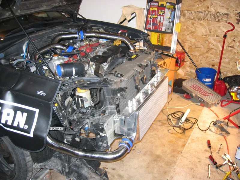

A 2004 WRX STI core in the middle of being fitted, pipes still open. The file calls it a front-mount. The frame shows the core and the plumbing. It does not show the temperature of the air in those pipes.
The squeeze spends work as heat
NASA’s compressor note is written for a jet engine. Raising the pressure means doing work on the air. With no heat added or removed during that rise, the total-temperature ratio follows the pressure ratio. For air the specific-heat ratio is about 1.4, so a pressure ratio above 1 brings a temperature ratio above 1. The air leaves hotter than it entered. A real compressor’s efficiency is always below 1, and the work equation divides by that efficiency, so the same pressure ratio costs more work than the ideal.
The ideal case has a number, and it is a different machine. NASA’s no-loss derivation, no heat leaving the gas and no friction, puts the temperature ratio at 1.219 when absolute pressure doubles. The specific-heat ratio there is 1.4, and the exponent is about 0.286. The slide is a pump filling a compressed-air rocket. Garrett’s automotive note does not use that ratio. It says the temperature depends on boost, engine speed, and turbocharger efficiency, and that in some cases the air is well above 200°C (392°F). Garrett puts the cooler between the turbo and the cylinders so that heat can come out before the charge is used.
Hotter air at the same pressure takes more room for the same mass. NASA’s equation of state on that compression page is pv = RT, and v is the specific volume. Hold the pressure and raise the temperature, and the volume per mass goes up. Garrett’s core page puts the practical result in the cylinders: hot air is less dense, so less of it can be fed in, and the cooler’s job is to take the heat out and make the charge denser. The same drop in intake temperature is how Garrett says the risk of detonation, or knocking, comes down. Density is the mass in the cylinder. Knock is the combustion. A manifold-pressure reading is neither one.
Outside air, or a coolant loop
An air-to-air core keeps the two streams apart. Garrett’s bar-and-plate cores send charge air through sealed passages in one direction and ambient air through a separate set at a cross-flow. The cold passages are not sealed and not pressurized. Outside air goes in, takes heat off the plates, and leaves into the bay. Conduction is the heat moving into the metal that touches the charge air. Convection is the air carrying that heat away. Garrett says the exchange continues while the car is moving, or until the core is heat-soaked.
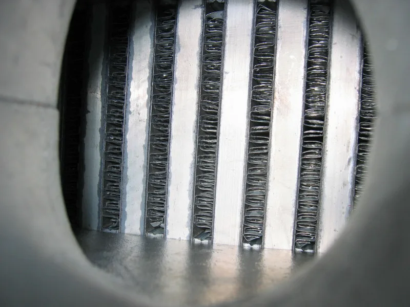

The open face of an air-to-air core, the metal the charge air has to give its heat to. The file calls it the interior of an air-to-air intercooler. It does not show whether the stack is bar-and-plate or tube-and-fin, and it does not show ambient air crossing the other set of passages.
On the Garrett cores, the cold-side span is short, about 3 to 5 inches, so those ambient-air fins are packed tighter. The hot run is longer, 11 to 28 inches on some of the cores, with a looser fin count, because that is the passage the charge air has to get through. Those inches belong to Garrett’s cores.
The same air-to-air job can sit over the engine instead of in the nose.
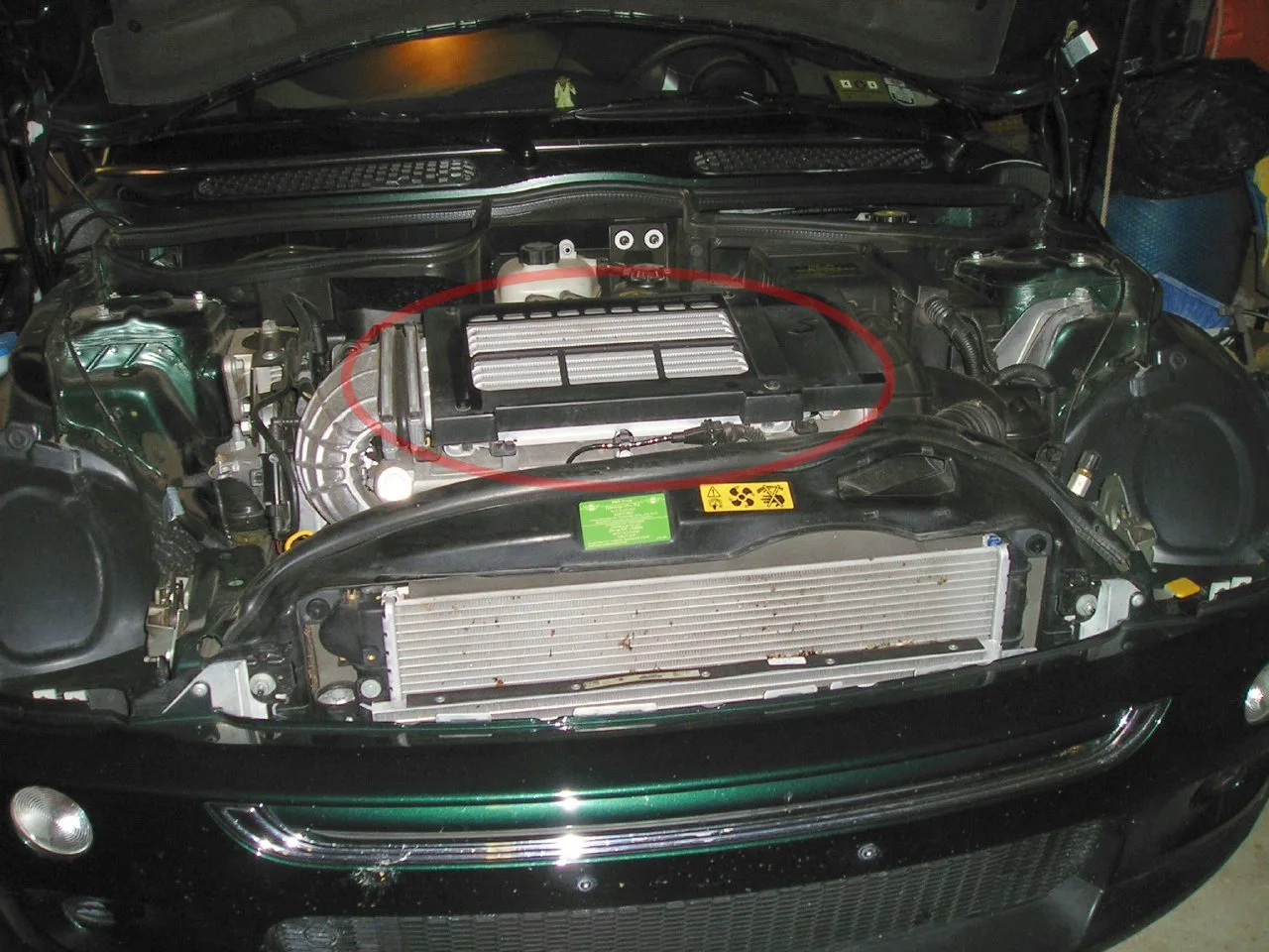

The silver core on this Mini Cooper S is the top-mount the file names. Charge air still has to cross metal that outside air can reach. The picture shows where the core sits. It does not show a scoop feeding it, and it does not show the core heat-soaked or cool.
The other design hands the heat to liquid before the outside air ever sees it. MAHLE’s indirect system puts the charge-air heat into a separate low-temperature coolant circuit. A low-temperature radiator on the engine cooling module then releases that heat to ambient air. MAHLE says that radiator can be designed more compactly than a direct charge-air cooler, because the transfer at the cooler is from air into coolant. Direct, in that account, is the heat going straight to the outside air, which is the air-to-air split above. The cascaded version of the indirect cooler is built into the intake pipe and uses two stages. MAHLE says it gives charge-air temperatures close to the coolant, with minimal pressure loss and a packaging advantage. Those words describe that intake-pipe unit.
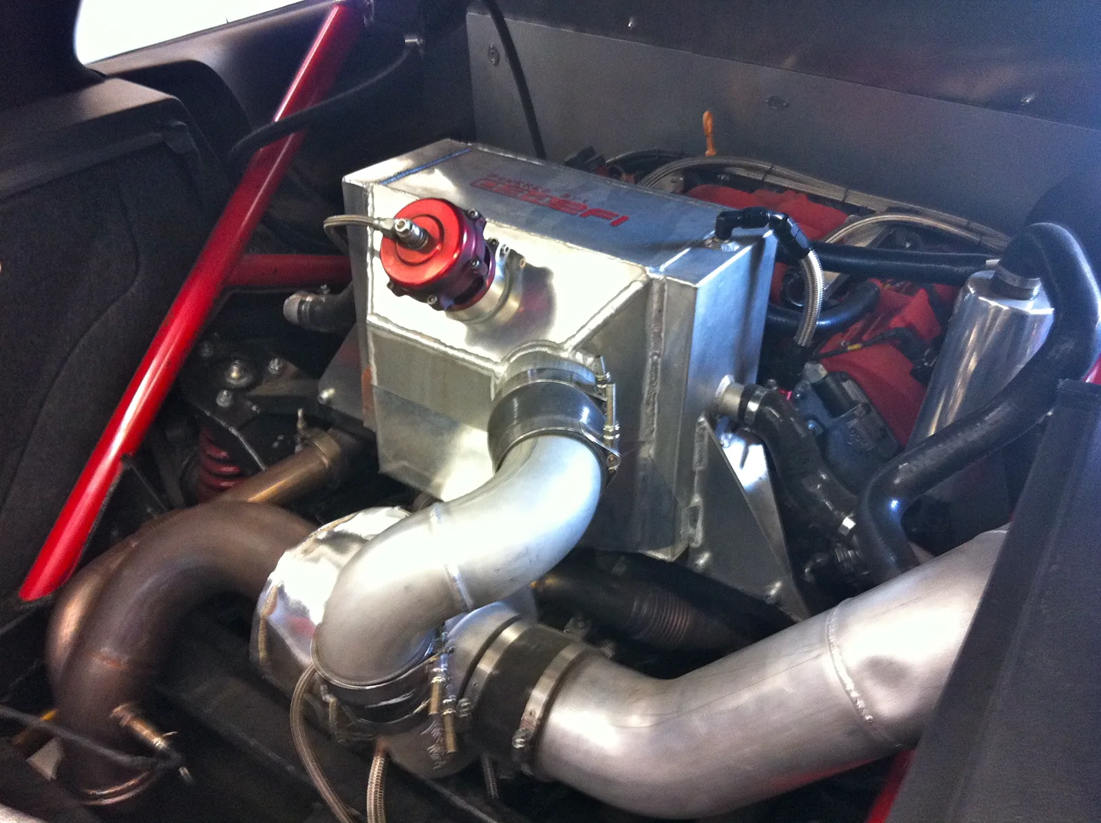

An air-to-liquid core beside a large turbo, hoses on the coolant side, in a mid-engine car. The file names the turbo a Garrett GT45R and the core the intercooler. The hoses are the liquid path. The frame does not show the low-temperature radiator, and this core is a separate unit, not the intake-pipe cooler MAHLE describes.
What the plumbing spends
Cooling costs pressure. Garrett’s definition of pressure drop is the difference flow resistance makes: pressure leaving the cooler lower than pressure going in. The turbo spins faster to make up the loss, so a manifold gauge can hide the drop, and the faster wheel heats the air. Fin density is the bargain on those cores. More fin, more surface, more resistance.
The pipes make the same bargain in diameter. Garrett’s tubing note sizes the duct so the charge runs at about 200 to 300 feet per second. A diameter tighter than the one for that speed raises the velocity and drops the pressure. A larger diameter lets the charge expand to fill the pipe, and the response when the throttle moves gets slower. The bend radius they want is more than 1.5 times the tube diameter, and the flow area should stay free of sudden steps. End-tank shape is part of the drop as well. A side entry spreads the air across the core. An over-the-top tank can starve the upper passages. Garrett’s line for the core itself is to use the largest one that fits the car. That is the cooling side of the choice. The response side is the volume those pipes and that core then have to fill.
How high the system is asked to hold pressure is a wastegate question. The cooler is downstream of that, and it spends some of the pressure on the way to the manifold.
Oil in the pipes, a seam that will not hold, a car standing still
Garrett’s leak check is a pressure test of the charge system. Clamps get checked for tightness. Couplers get checked for holes or tears. The cooler core and its end tanks get checked for voids in the welds. A core face that looks dirty in the bumper has not had that test.
Oil in the pipes has a short list, and the cooler is often where it shows up. Garrett says a properly installed turbo should not leak oil. Too much restriction into the compressor can pull oil past the compressor piston ring: a filter that is too small or clogged, or tubing that is too small or bent too many times between the filter and the compressor housing. The system note ties that leak to oil loss, a fouled intercooler, and smoke at the tailpipe. The Level 4 notes describe the pressure that lets it happen. A blocked filter can drop the pressure behind the compressor wheel below the pressure in the center housing, and oil goes past a ring that is still in good condition. A leak in the charge-air system, the hoses or the charge-air cooler included, can do the same. So can crankcase pressure high enough to keep the oil from draining, or a sump level high enough to cover the drain. Oil inside the cooler means oil reached the charge air. It does not pick the filter, the drain, the crankcase, or a split hose.
Heat soak is the other ordinary case, and it is not a leak. Garrett’s account of the air-to-air exchange runs while the car is moving and feeding the cold side, and it names the end of that exchange as a core that has heat-soaked. A car standing still with a hot charge and no fresh air through the face is that condition. The face will not show a torn coupler, and it will not show the oil.
Sources
- NASA Glenn: isentropic compression — Ideal no-loss compression, a temperature ratio of 1.219 when absolute pressure doubles for air, and the equation of state
- NASA Glenn: compressor thermodynamics — Work done on the flow, the temperature ratio that follows a pressure rise, and compressor efficiency below 1
- Garrett: how intercoolers work — Compression heat, cases above 200°C, density, and a lower risk of detonation
- Garrett: performance intercooler cores — Air-to-air cross-flow, fin density on Garrett cores, pressure drop, and heat soak
- Garrett: turbo system optimization — Charge-tube speed, end tanks, a fouled intercooler from inlet restriction, and the pressure test for leaks
- Garrett: Installer Connect Level 4 notes — Oil past the compressor ring from a blocked filter, crankcase pressure, a high sump, or a leak at the hoses or charge-air cooler
- MAHLE: passenger-car cooling — Direct heat to ambient air, the indirect low-temperature circuit and radiator, and cascaded cooling in the intake pipe
References checked .